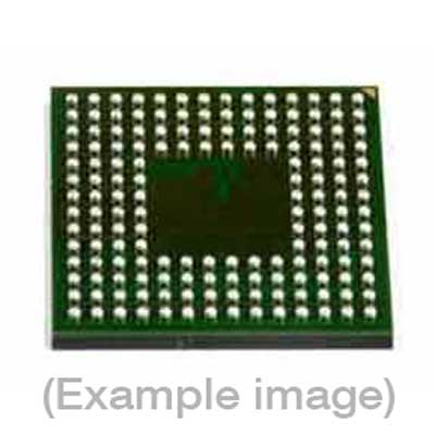
Adapters for Manual Programmers
| 9th Gen |
| FVESM1517BGA |
Adapters for Engineering Programmers
Last Updated: 05/18/2023
If the device is not yet supported by your BPM programmer (Generation), request Device Support
Note
IMPORTANT:
| Device Type: | Xilinx Virtex UltraScale FPGA |
| Device Memory Type: | eFUSE + Configuration Bitstream |
| Algorithm Programming Method: | JTAG + SelectMAP x16 |
| Serialization Supported: | No |
Memory Organization:
| Memory Type |
Attributes* |
Included in Default Range (Y/N) | BPWin Buffer Address (hex) |
| FUSE_RSA | R/W | Yes | 0000_0000 – 0000_002F |
| FUSE_KEY | R/W | Yes | 0000_0030 – 0000_006F |
| FUSE_USER | R/W | Yes | 0000_0070 – 0000_0073 |
| FUSE_CNTL | R/W | Yes | 0000_0074 – 0000_0077 |
| FUSE_SEC | R/W | Yes | 0000_0078 – 0000_007B |
| FUSE_USER_128 (FUSE_RES1) | R/W | Yes | 0000_0080 – 0000_008F |
| Configuration Bitstream-1 | R/W/E | Yes | 0000_0090 – 05C0_85A7 |
| Configuration Bitstream-2 | R/W/E | Yes | 0600_0000 – 0BC0_8587 |
| Default Algorithm Range | — | — | 0000_0000 – 08F9_0BB7 |
* R/W: verifiable and one time programmable (OTP). R/W/E: verifiable and re-programmable. Special Device Considerations:
| 1. | Each fuse is One-Time Programmable (OTP). |
| 2. | There are two SLR’s on this device and the master SLR is SLR0. For every fuse area except for FUSE_KEY the same value will be programmed to each SLR. |
| 3. | Each SLR may use a different FUSE_KEY value. In an NKY file key 0 maps to the master SLR which is SLR0 for this device. This means that key 1 maps to SLR1. SLR0 (NKY key 0) FUSE_KEY maps to Data Buffer Addresses [0000_0030h – 0000_004Fh]. SLR1 (NKY key 1) FUSE_KEY maps to Data Buffer Addresses [0000_0050h – 0000_006Fh]. |
| 4. | All fuse areas are MSB-to-LSB. For example FUSE_RSA[383:376] maps to Data Buffer Address [0000_0000h] bits [7:0]. Then FUSE_RSA[7:0] maps to Data Buffer Address [0000_002Fh] bits [7:0]. |
| 5. | Each valid fuse in FUSE_CNTL and FUSE_SEC maps to the Device Config Settings. Any fuses that do not map to valid values in FUSE_CNTL and FUSE_SEC will neither be programmed nor verified. |
| 6. | The FUSE_KEY values are verified and blank checked via CRC values. |
| 7. | The configuration bitstream is loaded at the end of Verify. The correct loading is then verified by the device driving the DONE_0 pin high. |
| 8. | FUSE_CNTL and FUSE_SEC are programmed after verifying the other fuse areas. Some of the fuses in FUSE_CNTL and FUSE_SEC may prevent stand-alone verification of the other fuse areas. |
| 9. | The configuration bitstream must be included in the Device Range for FUSE_CNTL and FUSE_SEC to be programmed. Both fuse areas are verified immediately after programming and at the end of Verify. |
| 10. | Any fuse area that is read secured prior to a re-programming attempt will fail Verify after Program and should be excluded from the Device Range. Stand-alone Verify will verify that the fuse area is secured. |
| 11. | If JTAG is disabled via FUSE_SEC[3] stand-alone Verify will verify that every fuse area included in the Device Range is read secured. |
| 12. | If using a configuration bitstream with RSA authentication please load the appropriate RSA key into FUSE_RSA and set FUSE_SEC[2] to ‘1’. This bit maps to Data Buffer Address [0000_009Bh] bit [2]. |
| 13. | If using a configuration bitstream with AES key obfuscation please use the key obfuscate values from the NKY file for the FUSE_KEY instead of the regular key values. Please also set FUSE_SEC[6] to ‘1’. This bit maps to Data Buffer Address [0000_009Bh] bit [6]. |
| 14. | FUSE_SEC[0] and FUSE_SEC[5] cannot both be programmed to ‘1’. The algorithm will check these two bits and fail if both are set to ‘1’. |
| 15. | For the configuration bitstream either an MCS or BIT file may be used. If using a BIT file please set ‘Reverse bitstream bit order’ to ‘Enabled’ in the Device Config Settings. |
| 16. | The configuration bitstream must have the correct sync word (32-bit aligned). If this is not detected within the first 256 bytes of the bitstream the algorithm will fail. The sync word will appear as either [9955_66AAh] or [AA99_5566h] if the bit order is reversed. |
| 17. | If loading a BIT file for the configuration bitstream please make sure that the sync word is 32-bit aligned. The file may need to be loaded at a Data Buffer Address besides [0000_0090h].It is recommended to remove the file header information (data prior to block of [FFh] values). |
| 18. | Due to the AES Key Rolling feature bitstream sizes may vary. This algorithm supports bitstream sizes up to twice the maximum length for the device. |
| 19. | This is a custom device selection. Please contact Xilinx before use. |
| 20. | This device selection requires the use of BP-2800 Enhanced FX800-SITE-C01. |
‘
BPM does not sell programmable devices, nor do we program devices directly. BPM makes programmers and accessories to make programming in-house fast, easy, and profitable.
Additional information
| 8-bit Bytes | 197166592 |
|---|---|
| Manufacturer | Xilinx |
| Packages | BGA(1517) |
| Part Number | XCKU115-2FLVA1517I |
| Set programming | Yes |
| Vcc(program) | 1.8 |
